![]()
 ½¤¤ù¦¡¤Æ¾Ç¹jÂ÷«Ê-ªkÄõ±µÀY
¡@
Diaphragm-Type
Chemical Seal
Flanged Diaphragm Seal
![]() ½¤¤ù¦¡¤Æ¾Ç¹jÂ÷«Ê-ªkÄõ±µÀY
½¤¤ù¦¡¤Æ¾Ç¹jÂ÷«Ê-ªkÄõ±µÀY
Flanged Diaphragm Seal
À³¥Î³õ¦X¡G
¤u·~¬yµ{À£¤O¿ö©ÎÀ£¤O¶Ç°T¾¹¤§¤Æ¾Ç¹jÂ÷½¤¤ù
Service:
Process industry chemical
seal to combine with pressure gauges and transmitters.
³]p¡G
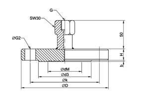
«¬¦¡A¡G¥»Åé»P¹j½¤ª½±µ³s±µ¡C
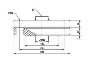
«¬¦¡B¡G¶}©ñ¦¡ªkÄõ¡A¤º³¡¹j½¤¡C
Design:
Type A: body with sealing face.
Type B: open flange with an internal diaphragm
¬yµ{³s±µ¡G
ªkÄõ¦¡¡CDN 15, 20, 25,40,50,80,100,125
DN 1/2, 3/4, 1, 1-1/2, 2, 3, 4, 5 per JIS, DIN, or ANSI
Process connection:
Flange DN 15, 20, 25,40,50,80,100,125
DN 1/2, 3/4, 1, 1-1/2, 2, 3, 4, 5 per JIS,
DIN, or ANSI
ÃB©wÀ£¤O¡G
¨£ªþªí¡C
Pressure rating:
See table
¾A¥ÎÀ£¤O½d³ò¡G
25 mBar©Î¥H¤W¡Aµø½¤¤ù¤Ø¤o¤Î¬yµ{ª¬ªp¦Ó©w¡C
Suitable pressure range:
25 mbar and up, depending on diaphragm size
and process condition.
¥»Åé¡G
¤£ù׿ûSUS 316¡C
ªkÄõDIN 2501¡A«Ê±JIS B 2212 RF, D DIN 2526, or ANSI B 16.5 RF
Body (process condition)
Stainless steel SUS 316.
Flange DIN 2501, sealing face form JIS B 2212,
D DIN 2526, or ANSI B 16.5 RF.
½¤¤ù¡G
¤£ù׿û§÷½è»P¥»Åé¦P¡A²k±µ¦Ü¥»Åé¡C
Diaphragm
Stainless steel, material same as body, welded
to body.
¤ò²ÓºÞ¡G
»P¥»Åé¤è¦V¡G¶b¦V³s±µ¡C
§÷½è¡G¤£ù׿û»P¥»Åé¦P¡A²k±µ¦Ü¥»Åé¡C
2B (DN50)¥H¤W¤§¤ò²ÓºÞ¡A¸Ë¸mÅ@ºÞ¡C
Å@ºÞ§÷½è¡GSUS 304
¼Ð·Ç©µ¦ùªø«×¡G1, 1.6, 2.5, 4, 6, 8, 10,
³Ì¤p¦±«×¡G50
Capillary extension
Axial entry capillary, same material as body,
welded to body.
For size greater than 2B (DN 50): armored.
Armor material: SUS 304.
Standard extension: 1, 1.6,
2.5, 4, 6, 8, 10,
Minimum curve radius:
»öªí±µÀY¡G
³s±µÀY¡G G1/2¥ÀÀY¡C²k±µ¦Ü¤ò²ÓºÞ©Î¥»Åé¡AµôÈ»P¥»Åé¦P¡C
Instrument connection:
Adaptor G1/2 female, welded to capillary or
body.
Material: same as body.
![]()
¥»Åé¡G
§÷½è¡GSUS 304, SUS
ªkÄõ«Ê±¡GJIS B 2212 FF, DIN 2526 E, C, or ANSI B 16.5 RFSF
Body (process condition)
Stainless steel SUS 304, SUS
Flange sealing face form: JIS B 2212 FF, DIN 2526
E,C, or ANSI B 16.5 RFSF.
½¤¤ù¡G
§÷½è¡GSUS 304, SUS
Å@½¤¡GPTFE¡A
PFA¶î§G¡A
Diaphragm
Stainless steel¡GSUS 304, SUS
Protection: PTFE ,
PFA
coated,
¤ò²ÓºÞ¡G
»P¥»Åé¤è¦V¡G®|¦V³s±µ¡C
«ü©w©µ¦ùªø«×¡G1
Å@ºÞ§÷½è¡G³n½èPE¶ì½¦Å@ºÞ¡C
Capillary extension
Radial entry.
Armor material: Soft PE armor.
Customer extension: 1
Minimum curve radius:
»öªí±µÀY¡G
³s±µÀY¡G ²k±µ¤f¡BºÞ¤úµuºÞ¡C
¨Ì«È¤á³W®æ¦w¸ËÀ£¤O¿ö¡C
¥N«È¦w¸Ë¦U¼tµP¶Ç°T¾¹¡C
Instrument connection:
Connector: welding or pipe tread pipeline.
Gauge as per customer¡¦s specification.
Transmitter mounting.
|
Type: A |
Type: B |
||||||||||||||||||||||||||||||||||||||||||||||||||||||||||||||||||||||||||||||||||||||||||||||||||||||||||||||||||||||||||||||||||||||||||||||||||||||||||||||||||||||||||||||||||||||||||||||||||||||||||||||||||||||||||||||||||||||||||||||||||||||||||||||||||||||||||||||||||||||||||||||||||||||||||||||||||||||||||||||||||||||||||||||||||||||||||||||||||||||||||||||||||||||||||||||||||||||||||||||||||||||||||||||||||||||||||||||||||||||||
|
¡@ ¡@ ¡@ ¡@ ¡@ |
¡@ ¡@ |
||||||||||||||||||||||||||||||||||||||||||||||||||||||||||||||||||||||||||||||||||||||||||||||||||||||||||||||||||||||||||||||||||||||||||||||||||||||||||||||||||||||||||||||||||||||||||||||||||||||||||||||||||||||||||||||||||||||||||||||||||||||||||||||||||||||||||||||||||||||||||||||||||||||||||||||||||||||||||||||||||||||||||||||||||||||||||||||||||||||||||||||||||||||||||||||||||||||||||||||||||||||||||||||||||||||||||||||||||||||||
|
¡@ ¡@ ¡@ ¡@ ¡@ ¡@ ¡@ ¡@ ¡@ ¡@ ¡@ ¡@ ¡@ ¡@ ¡@ ¡@ ¡@ ¡@ |
||||||||||||||||||||||||||||||||||||||||||||||||||||||||||||||||||||||||||||||||||||||||||||||||||||||||||||||||||||||||||||||||||||||||||||||||||||||||||||||||||||||||||||||||||||||||||||||||||||||||||||||||||||||||||||||||||||||||||||||||||||||||||||||||||||||||||||||||||||||||||||||||||||||||||||||||||||||||||||||||||||||||||||||||||||||||||||||||||||||||||||||||||||||||||||||||||||||||||||||||||||||||||||||||||||||||||||||||||||||||
![]()
qÁʮɽл¡©ú¡G«¬¦¡¡þ¤Ø¤o¡þ@À£µ¥¯Å¡þ¬yµ{±µÀY¡þ¼íÀ㳡§÷½è¡þ¤ò²ÓºÞ©µ¦ùªø«×¡þ¶ñ¥Rªo¡þ»öªí±µÀY¡þ¬yµ{±ø¥óµ¥¡C
Ordering information: Model / Size / Pressure rating
/ Process connection / Material of wetted parts / Capillary extension length /
Filling Liquid / Instrument connection / Process condition.
¥»«¬¿ý©Òz¸ê®Æ¬°¥Xª©®É¤§ª¬ªp¡A¥»¤½¥qÀH®É§ïµ½§ó·s²£«~¡A½ÐÀH®É¬¢¸ß¥»¤½¥q¡A¥H«KÀò±o³Ì·s°T®§¡C
The specification and dimension subject to change
without notice. Please contact us for latest product information.

![]()
¡@
¡@